


Highline Park NYC Video

Highline Park Design Video

Twelve Essential Steps to Net Zero Energy Video


If you have or know a solar project, please submit it to us for consideration as a featured project using Submit an Item. http://www.solaripedia.com/302/submit-an-item.html
Project
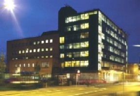
Daneshill House (UK)
Credits: ©2009 REVIVAL
Daneshill House is a purpose-designed local government office building which was constructed in the 1950’s as part of the Stevenage ‘new town’ development. The building has two distinct envelopes, the 1950’s, 6-storey (old block) area is a concrete framed building clad with single glazed steel curtain walling. It was refurbished in the 1980’s and 40% of the cladding which was single glazed had its thermal insulation improved with secondary glazing. The ‘new block’ areas of the building whilst still having a concrete frame and slab, have an insulated brickwork cladding with a relatively high U value of and small areas of windows which are high quality double glazed units with internal solar blinds. The old block areas have suffered in recent years from severe overheating in summer, which has been made worse by the insulation improvements in the 1980’s
A “Cooldeck” night cooling system utilizes the hidden mass of the building to provide summer cooling. ©2009 REVIVAL


Objectives
In 2002, Stevenage Borough Council decided to close its neighbourhood offices and centralise all staff within the main office, Daneshill House. To achieve this, it was necessary to increase the space efficiency by 20% whilst creating a modern and pleasant working environment. Daneshill house is a six storey, 1950’s building which was extended in 1985. Traditional refurbishment schemes for post war offices tend not to include the sustainable technologies that are used in new build offices. The Council wanted to demonstrate that a modern block could be sustainably refurbished to a high standard and adapted to utilise renewable energy generation. The objectives of the refurbishment were: Demonstration of energy efficient refurbishment of an existing office building Overall reduction of the CO2 by 50% compared to a similar ‘hypothetical’ existing building with the same use and occupancy levels To show that refurbishment is environmentally and economically more efficient than rebuilding Description of work The improvement works were categorized into four basic areas:
1. Old Block Refurbishment (floors two, three, and six) (namely the existing 6 storey area constructed in the 1950’s) · The conversion of existing cellular offices into modern IT based “open plan” office areas with new modular desking and high efficiency layouts that improve occupancy levels. This included the installation of: o Night cooling with Phase Change Material (PCM) o Solar and occupancy light controls o Top up mechanical cooling
2. New Block Atrium Refurbishment, ground and first floor (a two storey relatively modern office area constructed in 1980’s) · To improve occupancy levels, this area was converted to new high efficiency modular desking. This included altering existing air conditioning controls and BEMS to maximize ‘free cooling’ periods in summer and winter and the heating by using an adaptive temperature control regime and CO2 controls.
3. Customer Service Centre constructed in the 1980’s, (ground floor) · The Customer Services Centre is in the ‘new block’ area of the building and was stripped back to the structural shell before creating the new Customer Service Centre. The new installations included: o LED Lighting o Night cooling ‘top up’ to new air conditioning system to create a mixed mode system.
4. Solar Hot Water System · The new solar hot water system was installed as a ‘stand alone’ project and it provides ‘domestic’ hot water to all but approximately 1500m² of the 5,830m² building. The system included a new high efficiency condensing gas boiler and two 500litre calorifiers.
The common theme for all the areas is the use of thermal mass and night ventilation to provide summertime comfort cooling. In the 1950’s part of the building. It is also proposed to use ‘Phase Change Material’ to increase the thermal capacity of the building.In the public service area a new night ventilation passive cooling system incorporating phase change material will be incorporated as part of a new ‘hybrid’ air conditioning system. Low energy lighting with solar and occupancy controls will be include in the 1950’s block as well as the customer service area and a solar collection system will be installed for the existing electric hot water system.
Energy Efficiency
The existing light fittings in the atrium area were 20 years old and included floor standing, up lighters. The 100 existing uplighters were fitted with radio ‘wireless’ control switching, which provided three different levels of operation: individual, local and area. The main lighting in the office is now controlled by solar sensors, which turn off the lighting when sufficient daylight is available. The meeting rooms and open plan office areas have occupancy sensors and the centre rows of lights in the office operate on motion censors. The power consumption for the lighting on the third floor improved area has been measured as 38% better than a typical office. Air conditioning was deemed appropriate in some areas of the building including the ground and first floor atrium. Controls were improved and this, combined with the BEMS, has so far produced improvement in energy efficiency on the ground floor and on the first floor.
Heating/Cooling
Summertime overheating is a common problem in post war office buildings such as Daneshill House and the traditional approach is to install local mechanical DX air conditioning units that provide localised re-circulated cold air. However, this results in very uncomfortable conditions for those located close to the unit, particularly with the low ceiling heights that are typical for this kind of office building. This system also does not provide any extra ventilation and is often mistakenly used as a first option to cool an area, even when opening a window would be more effective. The Council wanted the refurbishment to be as environmentally friendly as possible and chose a system which made the best use of natural, free cooling. This system also allowed staff to open windows and avoided the cold draughts usually associated with traditional air conditioning systems. Cooldeck System A “Cooldeck” night cooling system, which utilises the hidden mass of the building, was chosen to provide summer cooling. It is designed to improve the transfer of thermal energy from the air to the concrete slab. During the summer, cool outside air is introduced into the offices by window fans at night. Duct mounted ceiling fans circulate this air under the CoolDeck elements to enable the cooling to be stored in the thermal mass. During the following day, the ceiling fans operate without the window fans to release the stored cooling. The system consists of a steel plate 1800mm long by 450mm wide fixed approximately 25mm from the surface of the concrete soffit with only the 450mm ends left open. A 150mm diameter spigot is fixed to the centre of the plate and this is connected to flexible ducting which delivers air from the room via an ‘in-line’ fan which serves two plates. The ceiling void acts as a plenum for the system and air is returned to the room via 200mm square open grilles fitted into the suspended ceiling tiles. In subsequent installations, phase-change material, (PCM) has been integrated with the CoolDeck elements to increase their thermal storage performance. The fans are controlled to operate at night, when the temperature the previous day exceeded 24ºC. Cool air is then delivered to the area through window fans which supply air from the east side of the building and extract it from the west side. However, night ventilation is held off when the internal temperature falls to 18ºC to prevent overcooling.
In the daytime, when the room temperature reaches 24ºC, the ceiling fans, (which operate on fast speed at night), run at slow speed to circulate warm air through the ‘Cooldeck’ plates and ceiling void. The air is cooled as it comes into contact with the concrete slab and then returns to the room through the open grilles in the ceiling tiles. The system has been enhanced by the use of highly efficient, solar reflective blinds which reflect a high degree of solar radiation and reduce solar heat gain. Staff has been instructed to close the blinds at night on the east side of the building to reduce increased heat caused by the early morning sun.
The system also demonstrates how the thermal mass capacity of the building can be increased by the inclusion of PCM into the cooling system. The PCM is a salt hydrate contained within foil pouches which lay on the “Cooldeck” plate so that the air passes between the concrete soffit and the PCM as shown below. The PCM “melts” or changes phase at 24ºC when placed in contact with the air on the surface of a room. As the air temperature in the room increases above 24ºC the heat flows into the PCM causing it to melt. Providing there is sufficient PCM, it continues to melt until the peak heat input has past, thus preventing overheating. However, as the PCM solidifies, the latent heat absorbed in the melting process is returned to the room, resulting in the room taking longer to cool down. In this way it performs in a similar way to thermal mass, but because of the heat involved it is very “concentrated”. The main advantage of PCM is that it increases the effective thermal mass of a building and requires less space that the equivalent “conventional” mass which makes it particularly useful in refurbishment projects as it can be retro installed. The design intention of the “Cooldeck” system is to increase the value of the heat transfer coefficient of the ceiling void from 2-3 W/m²k to around 15 W/m²k.
Mechanical ‘Top Up’ Cooling to Third Floor Old Block
The thermal modelling of the old block area had originally been carried out in the 1990’s using the ‘Heathrow Example Weather Year’. This exercise was updated using the ‘CIBSE Design Summer Year for London’ and the ‘London Test Reference Year’ following the exceptionally hot summers of 2003 and 2005. This new modelling exercise demonstrated that the old block floors would exceed the CIBSE and UK Building Regulations Part ‘L’ overheating criteria i.e. the temperature within the office must not exceed 28°C for more than 1% of the annual occupied period (approximately 20 hours per year). The solution to this problem was to install localised direct expansion (DX) refrigeration units within the ceiling void. The units (shown) were nicknamed ‘squid’ units due to their shape and the flexible ducting attached to the discharge side of the unit, that distribute cool air across the ceiling void. There are three squid units installed on the second, third and sixth floor old block area of the building and they represent approximately 25% of a traditional cooling load design (30 W/m² of cooling). The units are time controlled and switch on automatically when the office temperature rises above 27°C. One advantage of the squid design is that they can be hidden within the very narrow (220mm) ceiling void and the occupants are unaware of their presence or when they are operating. This, combined with the lack of any local control, should enable the operating periods of these units to be restricted to the design criteria and help to stop the mechanical cooling being used as ‘a first source of temperature reduction’ by the occupants.
Mixed Mode Cooling Using AHU and Night Cooling to Customer Services Centre
A full dynamic thermal modelling exercise was carried out as part of the design of the new Customer Services Centre (CSC) using IES Virtual Environment software. This analysis looked at the varying occupancy levels and the need to maintain the temperature between 21°C and 25°C. The final system comprises of a mixed mode mechanical ventilation and cooling system which uses a high efficiency Air Handling Unit together with the “Cooldeck” night cooling system to reduce the mechanical cooling load. Ventilation to the main office area of the CSC is provided by the air handling unit located in the existing adjacent garage. Cooling is provided by the ventilation supply air provided by this air handling unit, in conjunction with cooling provided by the “Cooldeck” units, which utilize the structural slab as thermal storage.
By utilizing the potential for thermal storage provided by the slab, in conjunction with phase change material (PCM), it is possible to minimise the requirement for mechanical cooling. During normal day-time operation the air handling unit supplies conditioned fresh air to fan units located within the ceiling void. These fan units supply the fresh air mixed with return air to the space via ceiling diffusers. The return air is drawn back from the space into the ceiling void. Exhaust air is extracted from the ceiling void by the mechanical ventilation unit. The supply temperature from the mechanical ventilation unit is modulated to provide cooling to maintain a maximum space temperature of 24°C. When the temperature in the space exceeds 24°C the thermal storage cooling is activated. Thermal storage fans located within the ceiling void draw return air from the ceiling void over the “Cooldeck” units. The air being drawn between the “Cooldeck” units and the structural soffit is cooled by the slab / PCM. This cooled return air is then mixed with the fresh air provided by the air handling unit and then supplied to the space by the fan units.
Controls Alterations to Existing Air Conditioning Systems
- Ground and First Floor Atrium Areas
A design study with full thermal modelling of the existing ground and first floor large modern open plan atrium areas was carried out in 2004. The purpose of the study was to establish if the air conditioning system could be run at night on a fan only basis to use the ‘free’ night cooling effect on the mass of the exposed structure and reduce the daytime cooling energy requirement. The study found that the fan energy used in the system was 42% of the total heating and cooling energy and running the fans at night would not provide any cooling efficiency advantage. The study did however show that an energy saving of 22% could be achieved with the installation of automatic damper controls. The control strategy was further developed to use summer and winter ‘Pre-Conditioning Periods’ as well as CO2, monitoring and an adaptive profile for the cooling set point temperature to bring the energy saving nearer to the intended 40%.
Hot Water
The original domestic hot water for the building, was supplied by two electrically heated 800litre capacity calorifiers on a “duty-standby” basis. These calorifiers were located in the basement plant room of the new office block built in 1985. They were heated by separate day and night-time electrical heating elements, each rated at 9kW.
The domestic hot water was supplied to the wash room facilities via a pumped distribution system with secondary return. The water consumption rate varied between approximately 800 litres and 1200 litres per day. The energy required to heat the water was also monitored and the average consumption level was approximately 85kWh/day. This equates to approximately 25.9MWh/year and an annual CO2 emission rate of 11.148 tonnes, based upon a fuel conversion factor of 0.43kg CO2/kWh. The main components of the new solar water system were two new 500 litre capacity high efficiency solar calorifiers located in the basement plant room of the new office block and three sets of south facing solar arrays on the roof of the same block.
The existing secondary pipe distribution system was retained and connected to the new hot water generating system. A pumped solar circuit is connected to the lower high efficiency heating coil of each calorifier, with a ‘back-up’ Class 5 gas fired high efficiency condensing boiler connected to the upper coil of calorifier No1. Calorifier No 2 is used as pre-heat to calorifier No 1. The solar collectors are all-glass, evacuated tubes with an absorber area of 18m2 and occupying a gross area of 22m2. The solar system pipe work is filled through a permanent filling station with approximately 120 litres of fluid containing an inhibitor and antifreeze. The system design flow rate is 13.5 l/min, with the flow to the three sets of collectors set at 4.5 l/min to ensure correct distribution of the fluid. The ‘Resol’ type ES controller constantly compares the temperature of the solar collectors with the temperature of the water in the calorifiers. Any time the solar collector temperature is higher than the stored water in either calorifier, the controller switches on the appropriate variable speed solar circulating pump to heat the water.
Lighting
The Light Emitting Diode (LED) lighting scheme for the public area of the Customer Services Centre was designed to provide a visually striking lighting effect with low maintenance. If LEDs are designed and controlled appropriately they can have a long life with little maintenance. The Daneshill House system consists of a series of modular LED strips hidden within a purpose made up-lighting trough ceiling system. The LED’s consist of three modules - white, blue, and blue and white. They are linked in series and connected to LED drivers and DMX controllers mounted in a custom rack within the CSC mezzanine plant room. The LED lighting is supplemented with compact fluorescent light fittings and perimeter cold cathode feature lighting. So far, the LED lighting system has not delivered energy savings over the previous, traditional lighting system. Innovative Technologies The Daneshill House project demonstrates:
· How a ‘night cooling system’ can be installed in a traditional office building with little exposed structural mass, to provide summer cooling with the addition of Phase Change Material (PCM).
· How a ‘night cooling system’ can be enhanced to create a ‘mixed mode’ system to deal with extreme overheating caused by exceptionally hot summers.
· Consideration of occupancy performance in relation to the building’s energy performance. The refurbishment design has increased the occupancy density and allowed a number of smaller less energy efficient offices to be closed.
· How renewable energy generation can be incorporated in a post war office building. The existing electrically heated hot water system was replaced with a large solar hot water system which is now supplying hot water to 3840m2 and 350 occupants.
· The installation of one of the first LED lighting schemes in the UK.
· A solar and occupancy controlled lighting system, plus alterations to the operating system and Building Environment Management System (BEMS) controls in an existing air conditioned area of the building. Completed building The energy performance of the “Cooldeck” system on the third floor old block has been measured and compared directly with traditional air conditioning systems. Potential savings of between 74% and 80% were demonstrated during early monitoring and further studies are being undertaken to confirm these findings.
On 1st October 2008, it became a requirement in for all public buildings England and Wales with a useful floor area exceeding 1,000 m2 to have a Display Energy Certificate (DEC). Daneshill House has a DEC with an ‘F’ rating. It was subsequently reported that of the UK buildings in possession of a DEC on 1st October 2008, 25% had achieved either an ‘F’ or ‘G’ rating. The average rating was ‘D’, with less than 1% achieving an ‘A’ rating. This was a little disappointing considering the additions that have been made during the refurbishment.
However, as the building relies on some air conditioning and has two non-refurbished old block floors with electric underfloor heating, it was felt that these factors had affected the rating. The calculation for the DEC also makes no allowance for the operational efficiency of the building and the very high occupational density that has been achieved within the refurbished building.
Lessons Learnt
Client leadership is important in a project such as this, and it is also important to obtain the buy in of the facilities management team early on. Refurbishment solutions exist which can improve the heating/cooling elements of a building and make it more energy efficient. Electronic control systems can reduce energy usage and provide monitoring data at the touch of a button. Using new technology can be difficult and this can be particularly true with refurbishment works. The LED lighting installation in the Customer Service Centre was one of the first such systems ever installed and the extra burden that places on the design and construction team cannot be overstated. The fact that almost every part of this system was bespoke turned an interesting idea into a very expensive and time consuming reality.
Commissioning problems have been prevalent throughout the Revival work packages and have caused difficulties in the monitoring stages. In future, installations the team would build in more time for commissioning and would conduct an extended period of post completion monitoring of both system performance and energy consumption. The most successful work package in the Stevenage project in terms of efficiency improvement, energy saved and commercial viability is the improvements carried out to the existing air conditioning systems in the Atrium area.
Whilst the adoption of new and innovative technologies are essential to reducing carbon emissions, this relatively simple and effective way of using energy more efficiently, clearly demonstrates that small improvements to existing buildings can have a large impact on reduction of carbon emissions. Future Steps Since the new systems were installed, Stevenage has experienced quite cool summers and so the systems have not been fully tested.
For this reason, Stevenage Borough Council will continue to gather data which can be used to analyse the efficiency of the system and the carbon emissions saved. Monitoring Stevenage Borough Council aimed to demonstrate improvements in energy performance against a target CO2 reduction of 50%. They also wanted to show efficiency improvements in terms of the buildings energy performance (KWh/m2) and space utilisation efficiency (KWh/person) and are comparing pre and post occupancy levels and energy performance in terms of occupancy density.
In addition, the solar thermal energy generation, whole building occupancy hours and hot water consumption are also being closely monitored. The monitoring programme consists of a combination of consumption monitoring for the whole building and detailed consumption and condition monitoring for a number of selected areas where improvements are being carried out. The monitoring data is collected in terms of “occupancy performance” or CO2 per person per year or CO2 per person whilst the building is occupied.
The project is made up of a number of individual elements which are a small part of a multi phase improvement programme covering less than 50% of the building. For this reason the monitoring programme was tailored to suit the particular areas of improvement and “whole building” needs to be interpreted with a clear understanding of the timing and extent of the overall project. The monitoring method is based upon the establishment of a comprehensive schedule of over 60 monitoring points and referenced monitoring data. This allows the monitoring exercises to be easily repeated. Internal environmental conditions are continually monitored and displayed throughout the refurbished offices showing both the CO2 levels and room temperatures.
The solar water heating is automatically monitored and a large scale electronic display in the Customer Services Centre provides a continual, visual update on the systems performance. The electronic display board shows the temperature of the solar collectors, stored hot water and cumulative thermal energy produced by the system. The solar hot water system installation is considered to be exemplary and is delivering the expected efficiency improvement over the previous electrically heated system.
During 2007, the system produced some 9,707kWh of solar energy and including the change from electricity as the main source of energy to gas as the auxiliary heat source, the system achieved an overall 58% reduction in CO2 emissions The team have also monitored the amount of clear sky either from direct observation or through the Met Office website so they can gauge the efficiency of the solar hot water system. All of this information can then be compared to previous efficiency and CO2 data from the building before the new technologies were installed. All of this information is analysed by the building energy management system which is then used by the Building Services Manager to make any necessary adjustments to the various engineering systems.
